

PAIO-(30-50)KW/(114-157)KWH Mobile Solar Container Technical Solution
Features
Extremely Simple
ALL IN ONE design, high integration, built-in force transmission device, saving time and labor Modular installation, simple structure, easy maintenance and construction
Standard 20-foot container mobile design, easy transportation and flexible layout
Overall delivery, whole machinery transportation, easy installation and operation and maintenance Power expansion and capacity expansion are achievable
Safe
Thermal runaway risk warning design concept Fire proof: perfluorohexanone gas
BMS and EMS linkage protection to higher improved safety
Intelligent
Cloud platform management system, supports remote/local monitoring, intelligent cloud operation and maintenance without expert on-site maintenance
Intelligent balancing strategy, system AI warning, ensure the consistency of the battery throughout the life cycle Support black start function, reliable power supply in both off-grid/on-grid modes
Stable
Dustproof and waterproof: IP54
Intelligent temperature control: industrial air conditioning, with cooling, heating, dehumidification, constant temperature, constant humidity and other functions
Relative humidity 5~95% without condensation Working temperature -30℃~55°C
Altitude 3000M
Can operate stably under various harsh natural conditions such as plateaus and deserts
System Standards
GB/T 4942 Enclosure protection degree (IP code) GB 2894-2008 Safety signs (ISO 3864:1984)
GB/T 50796-2012 Acceptance specification for photovoltaic power generation projects
GB/T 19964-2012 Technical regulations for photovoltaic power station access to power system GB 50217-2018 Power engineering cable design specification
GB/T 50054-2011 Low voltage power distribution design specification GB/T 50065-2011 Grounding design specification for AC power devices GB/T 36276-2018 Lithium-ion batteries for power storage
GB/T 34133-2017 Technical regulations for energy storage converter detection
System Technical Parameters

1. PAIO-(30-50)KW/(114-157)KWH container energy storage system parameters
| Product Capacity | 30KW/114KWH | 40KW/129KWH | 50KW/157KWH |
| Solar Input | |||
| Max Solar Input Voltage | 1000V | ||
| Rated Input Voltage | 600V | ||
| Solar Power | 33KW | 41.4KW | 52.4KW |
| MPPT Voltage Range | 150-850V | ||
| Start Voltage | 180V | ||
| Max Input Current | 3*40A | 4*40A | |
| MPPT Max Strings | 3/6 | 4/8 | |
| AC Output (Grid) | |||
| Max Output Power | 30KVA | 40KVA | 50KVA |
| Rated Output Power | 30KW | 40KW | 50KW |
| Rated Voltage | 3/N/PE, 220V/380V 3/N/PE, 230V/400V | ||
| Rated Current | 45.6A/43.3A | 60.8A/57.7A | 76A/72.2A |
| Rated Frequency | 50Hz/60Hz | ||
| Power Factor THDI | <3% | ||
| Power Factor | >0.99(0.8 超前. 0.8 滞后) | ||
| AC Input (Grid) | |||
| Max Bypass Current | 91.2A/86.6A | 121.6A/115.4A | 152A/144.4A |
| Rated Input Voltage | 3/N/PE, 220V/380V 3/N/PE, 230V/400V | ||
| Rated Input Frequency | 50Hz/60Hz | ||
| AC Output (off-grid) | |||
| Max Output Power | 30KW | 40KW | 50KW |
| Rated Output Voltage | 3/N/PE, 220V/380V 3/N/PE, 230V/400V | ||
| Rated Current | 45.6A/43.3A | 60.8A/57.7A | 76A/72.2A |
| Total voltage harmonic distortionTHDU | <2% | ||
| Rated Frequency | 50Hz/60Hz | ||
| Overload Ability | 110% Constant | ||
| Max Output Power | Constant 1.6 times power for 2s | ||
| On Grid-Off Grid Switch Time | <10ms | ||
| Battery | |||
| Rated Capacity(wh) | 114.6KWH | 129KWH |
157.6KWH |
| Rated Voltage | 409.6 | 460.8 | 563.2 |
| Max Charge Power | 30KW | 40KW | 50KW |
| Max Discharge Power | 30KW | 40KW | 50KW |
| Battery Thermal Management | Air cooling/heating | ||
| General Parameters | |||
| Weight | / | / |
约 15T |
| Working Temperature | -20℃ to 55℃ | ||
| Humidity | 0~90% non-condensing | ||
| Protection Level | IP54 | ||
| Noise | <70dB | ||
| Altitude | 3000m (derating above 3000m) | ||
| Cooling method | Air Cooling | ||
| Display and Communication | |||
| Display | LCD Screen | ||
| BMS Communication | RS485 CAN | ||
| EMS Communication | RS485 TCP/IP | ||

Figure 2: Partial diagram of PAIO-(30-50)KW/(114-157)KWH container energy storage system

Figure 3: Top view of PAIO-(30-50)KW/(114-157)KWH container energy storage system
1.1 PV Panel Parameters
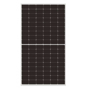
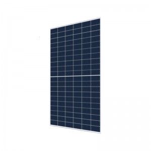
High efficiency: Module efficiency reaches over 21%. It can still work in low sunshine conditions. Foggy and cloudy days do not affect the power generation efficiency.
Reliable: The design life is more than 25 years, revolutionary packaging technology, long-lasting bonding, and the firmness is comparable to the building curtain wall. It has excellent mechanical load capacity, has passed the salt spray and other weather resistance tests and enhancements, and can withstand 2400pa wind load and 5400pa snow load.
Environmental protection: no pollution. Easy to maintain
LF460M10-60H parameter table: Table 2
| Product Model | LF460M10-60H |
| Output Power | 460W |
| Power Tolerance | 0-5W |
| Module Efficiency | 21.30% |
| Max Voltage | 34.93V |
| Max Current | 13.17A |
| Open-Circuit Voltage | 41.98V |
| Short-Circuit Current | 13.96A |
| Short circuit current temperature
coefficient (%/°C) |
0.046 |
| Open circuit voltage temperature
coefficient (%/°C) |
-0.266 |
| Power temperature coefficient
(%/℃) |
-0.354 |
| Module Work Temperature NMOT
(℃) |
43±3℃ |
| Module Size | 1904*1134*30mm |
| Weight | 23.5kg |
| Cable | 4mm2 |
| Glass | High transparency tempered glass 3.2mm |
| Junction Box | IP68, 3 bypass diodes |
| Terminal Blocks | MC4 |
| Max System Voltage | 1500V |
| Max System Fuse Value | 25A |
| Mechanical load | 5400pa |
| Work Temperature | -40 to 85℃ |
| Application Level | A |

Figure 4: Solar panel dimensions

Figure 5: Solar Panel Photo

Figure 6: Schematic diagram of solar panel installation (angle adjustable)
1.2Energy Storage Inverter
Adopt three-phase high-voltage energy storage inverter
4-way MPPT and 8 strings of 20A single string current, up to 96kW photovoltaic input Dual way battery port provides maximum 140A/70+70A charge and discharge current Support 160%/2s rated power load capacity of Backup port
Support 6 devices in on-grid and off-grid conditions
Support direct operation as on-grid inverter without battery
Support two generator access methods, with remote control start and stop function
Support peak control in self-generation and self-use mode and generator mode
Inverter Parameters: Table 3

1.3. Battery Grouping Solution
A high-capacity, high-safety, long-life lithium-ion battery for energy storage developed based on more than ten years of core intellectual property and technology accumulation in lithium iron phosphate and related materials. It has the characteristics of good cycle life, large single-cell capacity, high safety, high consistency, and its performance indicators in all aspects have reached the international leading and domestic advanced level.
Table 4
| Battery Cell | LFP (Lithium Iron Phosphate) |
| Rated Capacity | 280ah |
| Rated Voltage | 3.2V |
| Standard Charge Current | 0.5C |
| Standard Discharge Current | 0.5C |
| Charge End Voltage | 3.65V |
| Discharge End Voltage | 2.5V |
| Work Temperature | Charge 0 to 55℃,Discharge -20 to 55℃ |
| Cycles | 8000 cycles(@70%) |
| Battery Weight | 5.5±0.3kg |
Battery Module Parameters
The battery adopts a highly integrated standardized module, which is convenient for debugging and installation. Each standard box has 16 strings of batteries, 51.2V/280Ah.
The box can be installed with a fan for more effective heat dissipation. The BMS can automatically control the fan according to the temperature.
Table 5
| Single Battery Module Energy | 14.336KWH |
| Single Battery Module Voltage | 51.2V |
| Single Battery Module String | 16 cells in series |
Battery cluster/system assembly
The battery box is installed on the battery rack. The entire battery rack is welded with high-strength, thickened square steel, which is wear-resistant, corrosion-resistant and fire-resistant. The box surface is fully sprayed with insulating paint to effectively improve the insulation level. The box adopts an insulated closed installation, which can effectively prevent dripping water and dust from falling into the battery pack and has good heat dissipation performance. The system is divided into 1 cluster, which is neatly and evenly distributed on both sides of the energy storage cabinet. Each cluster of batteries consists of 8 standard battery boxes and 1 high-voltage box. The battery warehouse mainly includes battery packs, battery racks, BMS control boxes, cooling fans, etc. The battery needs to be equipped with a corresponding BMS management system. The type of battery is iron-lithium battery. The heat dissipation air conditioner is adjusted in real time according to the temperature in the warehouse.
Table 6
| Battery System Module Quantity | 8 | 9 | 11 |
| Battery System Total Strings | 128 | 144 | 176 |
| Battery System Total Energy | 114.6KWH | 129KWH | 157.6KWH |
| Battery System Total Voltage | 409.6V | 460.8V | 563.2V |
| System Rated Capacity | 280ah | 280ah | 280ah |
| Constant Discharge Current | 140A | 140A | 140A |
| Constant Charge Current | 140A | 140A | 140A |

Figure 8: Schematic diagram of battery system assembly
1.4 Thermal management and air conditioning parameters
The Energy Storage cabinet is equipped with an air conditioning cooling system and a cooling duct to control the temperature inside the energy storage cabinet.
The air conditioning system is connected to the battery management system (BMS) through the RS485 communication protocol.
In addition to realizing the linkage between the air conditioning and the fire protection system, the BMS should also be able to set the air conditioning start-up cooling point, cooling deviation, start-up hot point, heating deviation, battery cell temperature start-up cooling point, battery cell temperature start-up hot point and other parameters.
It has the function of manually starting the air conditioning operation and being able to control the air conditioning according to the battery cell temperature. The set battery cell temperature start-up cooling point and battery cell temperature start-up hot point parameters do not need to be sent to the air conditioning system. They are only the thresholds for the energy management system to control the air conditioning operation according to the battery cell temperature.
When the BMS detects that the battery temperature reaches a certain limit value, the BMS sends a command to the air conditioning system to control the air conditioning system to start running and control the temperature of the energy storage cabinet system within the appropriate temperature.
In the outdoor natural environment, the temperature and humidity in the energy storage cabinet can be adjusted, and the control and adjustment parameters are as follows: When the battery compartment is in operation, the temperature in the battery compartment is controlled within 35°C, the temperature difference in the local position is less than 5°C, and the humidity in the compartment is controlled within 70%.
Air Conditioner Parameters: Table 7
| Model No. | Industry ECSeries | Unit | 1100W | 1500W | 2000W |
| Size and Installation | Dimension | mm | 783*479*200 | 783*479*200 | 783*483*200 |
| Weight | Kg | 27.5 | 27.5 | 35 | |
| Installation | Flush Mount | ||||
| InstallationEnvironment | Outdoor | ||||
| WorkTemperature | ℃ | -40 to 55 | |||
| Environment and protection | Noise | dB | 65 | ||
| Lifespan | year | >10 | |||
| Protection Level | IP55 | ||||
| Cooling /heatingcapacity | W | 1100/800 | 1500/1000 | 2000/1000 | |
| performance | Power supplyrange | 220±15%VAC/50Hz | |||

Figure 9: Industrial Air Conditioner Diagram
Figure 10: Industrial air conditioner
1.5. Battery Management System
BMU Battery Module Management Unit (Level 3)
Responsible for collecting real-time information such as voltage and temperature of battery modules. At the same time, it performs equalization management, online detection, fault diagnosis, etc.
SBCU Battery Cluster Management Unit (Level 2)
Responsible for managing a cluster of battery packs, collecting battery operation information, fault diagnosis and alarm, battery equalization strategy analysis SOC calculation, insulation detection, relay adhesion detection, control of related relays, data communication interaction with BMU, etc.
MBCU Battery System Management Unit (Level 1)
Responsible for the management of the overall battery system. Complete battery status collection, analysis, monitoring and scheduling; battery system SOC, SOH calculation; system fault diagnosis and alarm; system power on and off and charge and discharge strategy management; and touch screen PCS/EMS data interaction.
Realize battery information display, provide a friendly manual operation interface, can easily help maintenance personnel locate problems, and provide an operation interface.
1.6 Energy management systems
The energy management system is an important part of the control system, which provides data management, monitoring, control and optimization for the scheduling control center to ensure stable and efficient operation of the system. The energy management system provides power and voltage set points for each distributed energy controller within the system; ensures that the demand for heat and electricity loads in the system is met, and ensures that the system meets the operating protocols with the main grid system; and minimizes energy consumption and system losses as much as possible.
The system is capable of real-time and timed data acquisition of all monitored operating parameters and statuses. All electrical quantities are sampled by AC and high accuracy and speed are guaranteed, and important historical data are processed and stored in the database.
Acquire the total voltage, current, average temperature, SOC, SOH, charging and discharging current and power limit,
single battery voltage, single battery temperature, equalization status of each battery, fault and alarm information, historical charging and discharging power, historical charging and discharging power, and other commonly used information of each group of batteries of BMS system. Collect relevant parameters of the PCS system, including DC voltage/current/power, three-phase active power, reactive power, three-phase voltage, three-phase current, power factor, frequency, IGBT temperature, RC filter temperature, operation status, alarms and faults and other commonly used information, as well as daily input power, daily output power, cumulative input power, cumulative output power, and so on.
Collects and displays various status quantities of the energy storage system, including the main circuit status (switch, accident trip signal, protection action signal, and abnormal signal), fire alarm, temperature development and other information.

Figure 11: Early warning systems

Figure 12 Energy overview (early data)

Figure 13. General overview of enterprise project operations (early data)
1.7 , Reducer drive unit
Reducer shell adopts casting process; high torque, low distribution speed, one side stroke up to
1.5 meters/minute, can finish putting away and putting away in 30 minutes (calculated according to one side 40 meters).
| Performance Parameters of Drive Reducer Table 8 | |||
| 1 | Reducer structure form | Planetary + parallel shaft, single input and dual output | |
| 2 | Reducer Model | GTX107L3-231-F2402 | |
| 3 | Rated output torque of reducer | 5000 | Nm |
| 4 | Maximum short-time output torque of thespeed reducer | 7000 | Nm |
| 5 | Rated output speed of reducer | 4.3 | rpm |
| 6 | Reduction gear ratio | 231.7 | |
| 7 | Reduction gear suitable for motor model | YVP-112M-6-2.2kW-B5-IP56 | |
| 8 | Motor power | 2.2 | kW |
| 9 | Theoretical motor output speed | 1000 | rpm |
| 10 | Reduction gear lubrication method | oil bath | |
| 11 | Recommended lubricants for speedreducers | ISO VG220/320 | |

Figure 15 Top view of reducer
List of main devices of the system.Table 9
| Product | Main Parameters | 30KW/114KWH | 40KW/129KWH | 50KW/157KWH | |
| Quantity (Unit) | |||||
| Container | 20 feet | 5.89*2.35*2.38 meters | 1 | 1 | 1 |
|
AIO Energy Storage System |
Energy StorageCabinet | 1*1.45*1.8 meters | 1 | 1 | 1 |
| Battery Module | 14.3KWH Module | 8 | 9 | 11 | |
| High VoltageModule | BMU+BCU | 1 | 1 | 1 | |
| Inverter | Power/Quantity | 30KW/1 | 40KW/1 | 50KW/1 | |
| Industrial AirConditioner | Power/ Quantity | 1.1KW/1 | 1.5KW/1 | 2KW/1 | |
| Fire ProofSystem | Built-in perfluorohexane fireextinguisher | 1 | 1 | 1 | |
| EMS | built-in | 1 | 1 | 1 | |
| Switch box | built-in | 1 | 1 | 1 | |
| Solar Panel | Solar Panel | Mono 460W | 72 | 90 | 114 |
| Bracket/Frame | 1*3 combination, hot-dipgalvanized | 26 | 32 | 40 | |
| force transmission (i.e. gearbox) | Speed reducer | Planetary + parallel shaft,single input and dual output | 2 | 2 | 2 |
| ElectricalMachinery | 380V 2200W | 2 | 2 | 2 | |
| Power Take-offTrack | 4m hot-dip galvanized | 4 | 4 | 4 | |
| Flat push outputtrack | 2m 3mm thickness, hot-dipgalvanized | Some | Some | Some | |